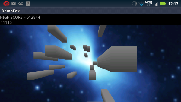
Figure 1: Image of the program running on a Motorola Droid Bionic XT875
Introduction
This article describes a modest 3D game ("Demofox") written for devices running the Android OS. While the scope of this game is limited (it has two levels and no enemies to fight), the code provided does address some difficult issues effectively, particularly in the area of user input.
The objective of game play is to direct a spaceship forward through a continuous series of obstacles (rectangular prisms) without contacting them. Forward flight (positive motion in the "Z" dimension) takes place at all times. The user is able to effect position changes in the X and Y dimensions, within limits. The perspective shown to the user is first person, with the spaceship itself not visible.
Figure 2 below shows a model of the game world. For clarity, this figure is rendered using parallel projection, whereas the game itself uses perspective projection with a vanishing point. As shown, movement is constrained to the interior of a long, tunnel-like rectangular solid of indefinite length in the "Z" dimension.
The obstacles faced by the user are rectangular prisms occupying discrete channels. Prisms reside completely within these channels, of which there are 16 in Figure 2. Though this is not shown in the model, prisms can touch one or more other prisms; more formally, the space between such prisms is zero.
The universe within which movement takes place in the model figure below is four prisms wide by four prisms high. In the real program as supplied, the universe is defined by a 14 x 14 matrix of channels, each of which contains random prisms of constant size, interspersed with the open areas through which the player must direct the spaceship as it moves forward.
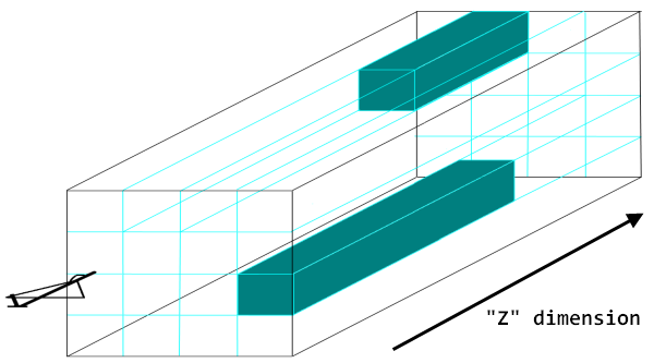
Figure 2: Model of game universe, rendered using parallel projection
As the user proceeds successfully forward, the score shown in the text control immediately above the main game display increments. When the user contacts an obstacle, the ship is pushed backwards slightly, and the score resets to zero. At this point, if the user has exceeded the previous high score, three short vibrations are emitted by the device as a notification mechanism. The high score resets to zero only when the device is powered off, or if the "Demofox" task is forcibly terminated. It is displayed at the very top of the game UI.
At program startup, the user is made to select between touchscreen and accelerometer-based play, and also to select between two levels. The button-based GUI that prompts the user for these pieces of information is landscape-oriented, as this is the mode of play that is prefered1. An image of this button-based GUI is shown below:
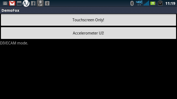
Figure 3: Button-based startup GUI, running on a Motorola Droid 4
The second level has a different background from the first level, and also has more obstacles. Accordingly, the user's score accrues more quickly in the second level. Figure 1 showed first level game play; a picture of second level game play is shown below:
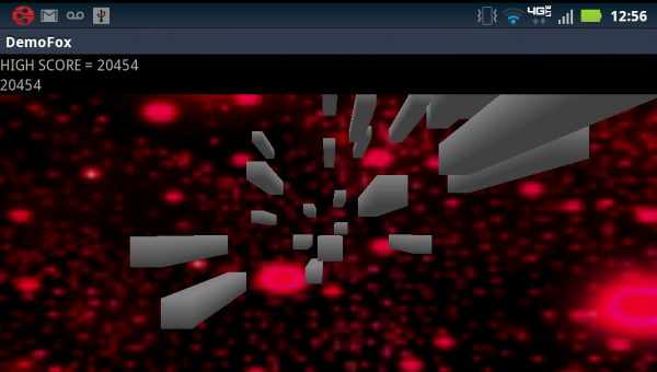
Figure 4: Image of the program running on a Motorola Droid Bionic XT875 (Level 2)
Portability
In general, libaries have been selected with maximum portability in mind. Only the "ES1.0" version of OpenGL is required, for example, and the Android version targeted is 2.1 or better. Similarly, touchscreen user input is supported, since some devices do not support accelerometer input. This is true of the emulator provided with the Android SDK, for example.
Despite its rudimentary nature, this emulator is fully supported by the code and binary files included with this article. A picture of the program running in the emulator is shown below:

Figure 5: Image of the program running on the Android SDK emulator
Installation
Two ZIP archives are provided at the top of the article: a "demo" archive and a "source" archive. The demo archive contains an ".apk" file. This is similar to an ".exe" file in the Windows OS, in that it contains executable code with some embedded resources (images). To run the Demofox game, it is necessary to copy the ".apk" file to some folder on the Android device file system. This can generally be done by connecting the device to a PC via USB, at which point Windows will give the user the option of browsing the Android file system using Explorer.
After the file has copied and the Android device has been disconnected, browse to the Android folder where the ".apk" file is located and tap it. The OS will give you the option of installing the application. It is necessary to enable a setting called "Unknown sources" / "Allow installation of non-Market applications" (or similar) in order to install an application in this way, but most versions of Android will allow you to change this setting interactively as needed when you attempt to install a non-market ".apk" file.
User Input
The simple game described in the last section is mildly amusing, but the area in which the author believes it really excels is that of user input. While the overall application described here is an arcade-style game, the user input techniques described should prove applicable to a wide variety of flight simulators of varying complexity and purpose.
The supplied program exposes two user interfaces: an accelerometer-based (or motion-sensing) user inteface and a touchscreen user interface. Accelerometer-based input devices have grown explosively in number since the introduction of the Nintendo Wii in late 2006. In particular, devices running the iOS and Android operating systems almost universally have multiple accelerometers. All of these devices offer the ability to construct a user experience that is closer to the real experience being modeled than is possible with a mouse, keyboard, or joystick.
The accelerometer-based user interface employed here is an example. It operates in two modes. One mode of operation allows the user to hold the device (e.g. a smart phone) like the control yoke of an airplane. Two of these are featured prominently in the next figure shown below. The user must pull back to point the nose up, push forward to point it down, rotate the device clockwise to effect a right turn, and rotate it counterclockwise to turn left. If an Android device running Demofox were attached to a dummy airplane yoke, its video output could be fed to a display in front of this yoke to create a sort of virtual reality.

Figure 6: Two yokes in a fixed-wing aircraft.
Strictly speaking, in accelerometer control mode, the Demofox user rotates the Android device about its longest axis to effect up-and-down movement. In a yoke like the one shown in the figure above, pulling back / pushing forward naturally causes the necessary rotation. This is part of the mechanical design of the yoke. The Android user operating without a dummy yoke, on the other hand, must take care to rotate the device, not just push it backwards and forwards. This is a familiar motion for many Android users, though, since many accelerometer-based Android user interfaces are based on axial rotation. At the Google Play store, many games that use such an interface have "tilt" in their names, like "aTilt Labyrinth 3D" or "Tilt Racing."
The little snippet of text below the buttons in Figure 3 relates to the other mode in which the accelerometer-based UI can operate: "Divecam" mode. The name of this mode draws an analogy with a diver holding an underwater camera as shown in the next figure below. Such a diver generally has the camera pointed in the direction in which he or she is moving, and this is similarly true of the Android device operating in "Divecam" mode. If the player wishes to navigate the Demofox ship toward the left, for example, he or she can do so by rotating the Android device as if he or she were taking a picture of an object to his or her left.
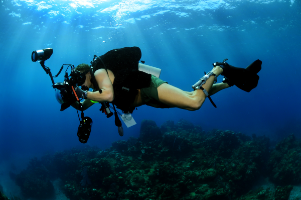
Figure 7: A diving camera
The selection between "Divecam" mode and "Yoke" mode is made by the user, but this is done indirectly. While the button-based GUI is showing, if the user holds the device like a yoke, i.e. basically perpendicular to the ground or floor plane beneath it, then the snippet of text below the buttons will indicate "Yoke" mode. If the user does not do this, then the text indicates "Divecam" mode. The mode in effect when the user presses a level selection button (i.e. when the user makes a selection on the second and final screen of the button-based GUI) is the mode used for game play. If the user chooses touchscreen mode, then this distinction is irrelevant.
The touchscreen input mode operates in a manner that should be familiar to Android users. To effect a maneuver to the left, the player must touch his or her finger down somewhere on the screen and drag it to the right. This is the same technique used to move toward the left edge of a zoomed-in webpage in the Android browser, to move toward the left in the Android version of Google Earth, and so on. Maneuvers in other directions are performed according to the same pattern: the user must touch down a finger somewhere on the screen and drag it in the direction 180 degrees opposite the desired direction. This results in a very intuitive mode of game play.
Architecture
Most basically, the code base supplied here is built around the principles of interface-based programming, and of modular programming, which relies on the use of interfaces. In keeping with these principles, the Demofox source consists of series of classes that communicate with each other exclusively using defined sets of methods.
Despite its use of the class keyword to subdivide code, the implementation provided is not really object-oriented, in several key senses. The author saw no need to use polymorphism beyond what is strictly required by the Java / Android infrastructure, for example. In fact, the same can be said about object instantiation; all members introduced by the author (as opposed to required overridden methods) are static.
This design offers the advantage of deterministic management of resources. These are allocated at application start, and reclaimed upon process termination, without any dependency on object instantiation or destruction.
Also, the author did not want to obfuscate the code presented in the article with architectural concerns. The design selected allows for a clear presentation of techniques that can be integrated into a wide variety of overall architectures.
Despite these simple structured programming underpinnings, every effort has been made to respect good programming principles. Most basically, the structured, procedural nature of the code is fully reflected in its declarations. Except where the infrastructure requires a true object instance, classes contain static members only, and any initialization that is necessary takes place in the static constructor. This article thus provides a good example of the proper syntax for procedural programming in Java.
Another design principle which is respected in the Demofox design is the principle of least privilege. Access modifiers (public, protected, etc.) are no more permissive than they need to be, and parameters are marked final wherever possible.
The principle of information hiding is also respected, in that the program consists of a series of classes that interact only by way of a functional interface. Only private fields are used, and the protected interface exposed by each class is comprised of a series of methods in a designated portion of each class.
Well-defined standards for the naming of members, and for the ordering of their declarations, were followed for all Demofox code. The member order used in the supplied source code files is shown below, from top to bottom:
- Constants
- Constructor (if strictly required)
public method overrides (if strictly required) protected methods private methods private fields static constructor
The listing shown above reflects the basic design already laid out. In keeping with least privilege, the only allowance made for any public member in the listing above is for overrides that are absolutely required by the Android / Java infrastructure.
Similarly, an instance constructor is only allowed for in the listing above if it is absolutely necessary. All of this reflects the overall design goal stated above, which was to implement a basic structured programming design, but to do so in a well-specified manner, and to adhere to general good practices.
The design used for this application is interface-based. Accordingly, each class's interface has a designated position in its file. This is the fourth item in the list shown above, "protected methods."
Naming standards are as shown in the listing below:
- "Lazy" case is used unless otherwise specified, e.g.
xbackplane
- Constant names are uppercase and are underbar-delimited e.g.
YOKE_UI_X_LIMIT
- Type suffixes are used for GUI elements, e.g.
highscoretv (a TextView)
- "Camel" case is used for
protected methods, if 2+ words are necessary, e.g. setScore()
- Abbreviations are generally avoided
- As shown above, type name suffixes for GUI controls are abbreviated.
- Local variable names can be abbreviated
- Units-of-measure can be abbreviated
- The word "alternate" is abbreviated "alt"
- The word "minimum" is abbreviated "min"
- The word "maximum" is abbreviated "max"
The author does not pretend that these naming and ordering conventions will be completely satisfactory for any other application. They represent his attempt to impose an appropriate but not stifling level of discipline on this relatively limited project. The same is true of the overall design selected. It is adequate for the author's purpose here.
Implementation
At the bottom level of the application architecture lies a class named cube. This class is capable of rendering cubes into the model world associated with an instance of type javax.microedition.khronos.opengles.GL10. In keeping with the interface-based architecture described above, this GL10 instance is passed into a static method, draw().
The draw() method draws a cube2 whose sides are 1.0 units in width, centered about the origin at (0,0,0). It is up to the caller to apply transformations to position each cube properly before the method is called. The cubes are drawn using a top-to-bottom gray gradient coloration; no texture is applied. This is a good, neutral building block for many 3D applications. In the Demofox application, groups of three cubes are used to create obstacles for the player.
Like all of the Demofox classes, the cube class begins with its local constant declarations. These are shown and discussed below. The first segment appears thus:
 Collapse | Copy Code
final class cube
{
 private static final int PRISM_FULL_COLOR = 0x08000;
 private static final int PRISM_HALF_COLOR = 0x04000;
These first two declarations define the brightness of the beginning and ending shades of gray used to render the cube. These are of type int, and will be used as OpenGL "fixed point" values. The values actually used above represent full brightness and 50% brightness. The code continues as shown below:
Collapse | Copy Code private static final float PRISM_CUBE_WIDTH = 1f;
private static final float VERTICES[] =
{
-PRISM_CUBE_WIDTH/2f, -PRISM_CUBE_WIDTH/2f, -PRISM_CUBE_WIDTH/2f,
PRISM_CUBE_WIDTH/2f, -PRISM_CUBE_WIDTH/2f, -PRISM_CUBE_WIDTH/2f,
PRISM_CUBE_WIDTH/2f, PRISM_CUBE_WIDTH/2f, -PRISM_CUBE_WIDTH/2f,
-PRISM_CUBE_WIDTH/2f, PRISM_CUBE_WIDTH/2f, -PRISM_CUBE_WIDTH/2f,
-PRISM_CUBE_WIDTH/2f, -PRISM_CUBE_WIDTH/2f, PRISM_CUBE_WIDTH/2f,
PRISM_CUBE_WIDTH/2f, -PRISM_CUBE_WIDTH/2f, PRISM_CUBE_WIDTH/2f,
PRISM_CUBE_WIDTH/2f, PRISM_CUBE_WIDTH/2f, PRISM_CUBE_WIDTH/2f,
-PRISM_CUBE_WIDTH/2f, PRISM_CUBE_WIDTH/2f, PRISM_CUBE_WIDTH/2f,
};
The constant PRISM_CUBE_WIDTH specifies the length of each side of the cube. Then, the lengthy array declaration shown in the snippet above defines the eight vertices of the cube in 3D space. Two possible coordinates, 0.5 and -0.5, are permuted across the three dimensions to yield 8 array elements.
It is not sufficient, though, to simply supply the eight vertices of the cube to OpenGL. Instead, 12 triangles must be drawn (two per face, times six cube faces), resulting in a 36-vertex sequence. OpenGL rendering is triangle-driven and does not work with rectangular faces. The next set of constant declarations take care of these details:
Collapse | Copy Code private static final int CUBE_VERTEX_COUNT = 36;
private static final byte CUBE_VERTEX_INDICES[] =
{
0, 4, 5, 0, 5, 1, 1, 5, 6,
1, 6, 2,
2, 6, 7,
2, 7, 3,
3, 7, 4,
3, 4, 0,
4, 7, 6,
4, 6, 5,
3, 0, 1,
3, 1, 2
};
Each of the elements in CUBE_VERTEX_INDICES is a number from 0 to 7, and uniquely identifies one of the 8 cube vertices. Specifically, these 0 to 7 elements are indices into array cube.VERTICES.
The coordinates for these faces are rendered, and therefore defined above, in a specific order that allows for a performance benefit. This ordering is such that the front faces (i.e. those that are visible in a given frame) end up getting drawn using a clockwise motion from each vertex to the next, whereas the equivalent motion for hidden faces ends up being counterclockwise. This allows OpenGL to cull (i.e. not render) the back faces of the solid.
The cube is a very easy example of this optimization. When defining the cube, we do so such that the vertices of the front face (the face lying entirely in the plane where Z = -0.5) is drawn in clockwise order, and the back face is drawn counterclocwise, assuming the camera is looking at the front face.
If we rotate the cube 180 degrees about the yaw ("Y") axis, and leave the camera in the same spot, then when these same three vertices are rendered, it will take place in a counterclockwise fashion. OpenGL, when configured to cull surfaces, deals with both scenarios by only drawing the clockwise renderings.
This brief discussion of surface culling necessarily leaves out some detail. Some more information about this technique is available in another of the author's articles on this site. Though that article uses Direct3D instead of OpenGL, the design techniques required are the same, and some of the illustrative figures used in that article may help make the text discussion above clearer.
After the declaration of these constants, the protected interface exposed by class cube is defined. This consists of two static methods, the first of which is draw():
Collapse | Copy Code protected static void draw(final GL10 gl)
{
gl.glDisable(GL10.GL_TEXTURE_2D);
gl.glEnableClientState(GL10.GL_VERTEX_ARRAY);
gl.glFrontFace(GL10.GL_CW);
gl.glVertexPointer(3, GL10.GL_FLOAT, 0, vertexbuffer);
gl.glColorPointer(4, GL10.GL_FIXED, 0, colorbuffer);
gl.glDrawElements(GL10.GL_TRIANGLES, CUBE_VERTEX_COUNT,
GL10.GL_UNSIGNED_BYTE, indexbuffer);
gl.glDisableClientState(GL10.GL_VERTEX_ARRAY);
}
The method implementation begins by disabling texturing, since the cube to be drawn is not textured. Then, two calls are made, which prepare the OpenGL rendering engine to receive vertices, and enable clockwise surface culling, as described above. The floating point coordinate buffer, and the fixed point color buffer, are supplied to OpenGL by the calls to glVertexPointer() and glColorPointer(). Then, glDrawElements() is used to effect the actual drawing of the cube, and a call is made to return the OpenGL rendering engine to its pre-call state.
The other protected method that is exposed by cube returns the width of a cube side. This is shown below:
Collapse | Copy Code protected static float getPrismCubeWidth()
{
return PRISM_CUBE_WIDTH;
}
This is used by cuber, for example, to translate channel numbers into OpenGL coordinates.
Many readers will likely be accustomed to a flow of information which is the reverse of what's shown here. Specifically, such readers might expect for a cube class to expose a property allowing its size to be set by the consumer of the class, accompanied, perhaps, by similar properties relating to color and texture.
Here, these values are instead contained within the cube class, and are selectively exposed via a defined interface. This is done only in cases where some specific consumer is known to require access.
While not an example of OOP, this design does respect several principles the author holds very important. The principle of least privilege is an example; Demofox does not need for cuber, demofoxactivity, touchableglview, etc., to manipulate the color or width of the solid rendered by cube, so these other classes are not allowed to do so.
Instead, the constants used to determine such things as cube color and width are colocated with the code that uses them most, and are hidden unless they specifically need to be exposed. The cuber class needs to read the width value, but not write it, and it is therefore granted this privilege only. Consistent with the interface-based approach promised earlier, access to this value is given by way of a method, not a field.
The code shown above also exemplifies modular programming. There is a strict separation-of-concerns between two key tasks: the generation of cubes, which is a generic and potentially reusable operation existing at a relatively low level, and their construction into groups of prisms and integration into the overall application, which is a higher-level task.
The cube class is self-contained. It does one thing well (renders a neutral cube using a gray gradient) and eschews all other roles (e.g. positioning the cube).
While the cube class is admittedly inflexible, it also is most definitely a component, or (literal) building block. To force some notion of adaptability onto it would be an example of speculative generality, and this is something the author considers it wise to avoid, at least for the expository purposes of this article.
All other executable code for the cube class resides in the static constructor. In each of the Demofox classes, the static constructor takes care of the allocation of application resources. For the cube class, this constructor begins as shown below:
Collapse | Copy Code static
{
final int fullcolor = PRISM_FULL_COLOR;
final int halfcolor = PRISM_HALF_COLOR;
final int colors[] =
{
halfcolor, halfcolor, halfcolor, fullcolor,
halfcolor, halfcolor, halfcolor, fullcolor,
fullcolor, fullcolor, fullcolor, fullcolor,
fullcolor, fullcolor, fullcolor, fullcolor,
halfcolor, halfcolor, halfcolor, fullcolor,
halfcolor, halfcolor, halfcolor, fullcolor,
fullcolor, fullcolor, fullcolor, fullcolor,
fullcolor, fullcolor, fullcolor, fullcolor
};
This initial portion of the static constructor is focused on coloration. First, the aliases fullcolor and halfcolor are created. Then, these are used to declare and initialize array colors. This array parallels array VERTICES. Each of the eight rows in its initializer corresponds to the similarly-numbered row in the initializer of VERTICES, and to the same cube vertex as that row. Where each row in VERTICES had three individual numeric coordinates, above, each row has four: red, green, blue, and alpha (opacity).
In examining the declaration of colors, consider that all of the vertices with lower "Y" coordinate values are gray, while vertices with higher "Y" values are white. This is what creates the gradient effect evident in the rendered cubes.
The static constructor for the cube class concludes with the code shown below:
Collapse | Copy Code final ByteBuffer vbb = ByteBuffer.allocateDirect(VERTICES.length * Float.SIZE
/ Byte.SIZE);
vbb.order(ByteOrder.nativeOrder());
vertexbuffer = vbb.asFloatBuffer();
vertexbuffer.put(VERTICES);
vertexbuffer.position(0);
final ByteBuffer cbb = ByteBuffer
.allocateDirect(colors.length * Integer.SIZE);
cbb.order(ByteOrder.nativeOrder());
colorbuffer = cbb.asIntBuffer();
colorbuffer.put(colors);
colorbuffer.position(0);
indexbuffer = ByteBuffer.allocateDirect(CUBE_VERTEX_INDICES.length);
indexbuffer.put(CUBE_VERTEX_INDICES);
indexbuffer.position(0);
}
This code sets up three data structures required for OpenGL 3D rendering. Member vertexbuffer holds the 8 coordinates of the cube vertices. This is basically a copy of VERTICES, in a very specific format. In particular, vertexbuffer is a direct buffer. In the nomenclature of Java, this means that it does not reside on the main heap, and will not get relocated by the Java garbage collector. These requirements are imposed by OpenGL.
Another direct buffer, indexbuffer, holds the 36 indices into VERTICES that define the way in which the cube is actually rendered. Again, this is basically just a copy of a more familiar-looking data structure, in this case CUBE_VERTEX_INDICES.
Finally, colorbuffer is a direct buffer copy of colors. Like the other two data structures for which a direct buffer gets created, colorbuffer contains data to which OpenGL requires quick access during rendering.
Other Classes
The other classes used for Demofox are fundamentally similar to cube in their construction. Each of them exhibits the same member ordering, naming conventions, and overall interface-based, structured philosophy. A listing of all Demofox classes is given below:
cube : See above. plane : This is similar to cube, but renders a flat plane defined by the equation Z=KK is some constant. It is used to render a background image for the game. cuber : This is a subclass of GLSurfaceView.Renderer, and it performs high-level management of the 3D rendering. It is the class that calls into plane and cube, for example. touchableglview : This is a subclass of GLSurfaceView, with methods overridden to facilitate the touchscreen UI. demofoxactivity : This is a subclass of Activity, and is thus the top-level unit of the application from a procedural standpoint. The main point-of-entry is defined here, for example.
The remainder of this article deals with those portions of these other classes that the author thought most noteworthy.
Prism Lifetime
One very significant role played by cuber is the generation and management of the prismatic obstacles. These are presented to the user in a continuous stream, as if they comprised a sort of permanent, asteroid-belt-like obstruction in space.
It would be sub-optimal to render such a huge conglomeration of figures with each frame, though. Only a small subset of these really needs to be rendered to provide a convincing game experience.
A simplistic way to optimize the generation of prisms might be to generate a small group of them, in near proximity to the user, at application start. These would be positioned in front of the user; in this case, that would place them at slightly higher "Z" coordinates than the user's ship. Under such a design, another, similar group of prisms would be generated after the user had passed by all of the first group. Also, at that time, the first group of prisms would cease to be rendered, and any associated resources would be deallocated.
This simplistic approach does create a stream of obstacles that is basically continuous, but it also suffers from gaps in the presentation of these obstacles. Typically, as a prism group passes out of view, there is a point at which the last prism of the group becomes invisible, and then the next group of prisms appears suddenly, all at once. This results in an unconvincing simulation.
The strategy actually used by Demofox, though, does rely on the basic narrative given above, despite its simplistic nature. The actual code given here compensates for the natural abruptness of the prism group transitions by rendering two such groups at once, and staggering them such that the transitions between groups are much less obvious.
In essence, the approach actually used is identical to the simplistic approach described, but involving two sets of prism groups. The second of these groups does not start getting rendered until the user has reached a certain "Z" coordinate, cuber.START_ALT_PRISMS. After that, groups are regenerated as they have completely passed the user in the "Z" dimension.
To be specific, this regeneration process is handled by calling the reset method of class cuber.This method begins as shown below:
Collapse | Copy Code private static void reset(final boolean alternate)
{
if (!alternate)
{
paging = getPositionstate() - demofoxactivity.getStartDistance();
xstate = new ArrayList<Integer>();
ystate = new ArrayList<Integer>();
zstate = new ArrayList<Integer>();
for (int index = 0; index < simultaneaty; ++index)
{
xstate.add(RANDOM_GENERATOR.nextInt(PRISMS_PER_DIMENSION)
- PRISMS_PER_DIMENSION / 2);
ystate.add(RANDOM_GENERATOR.nextInt(PRISMS_PER_DIMENSION)
- PRISMS_PER_DIMENSION / 2);
zstate.add(RANDOM_GENERATOR.nextInt(PRISMS_PER_DIMENSION)
- PRISMS_PER_DIMENSION / 2);
}
}
First, note that the portion of reset()shown above pertains to the first set of obstacle prisms, i.e. the one that was present even in the simplistic algorithm given above, before the second set of obstacles was added to improved continuity. The outer if shown above has an else clause which is very similar to the if clause shown above, but uses its own set of variables (altpaging instead of paging, altxstate instead of xstate, and so on3).
Most of the code shown above takes care of resetting the first obstacle group into new positions after it has passed out of view. To begin, member paging is set to the current "Z" position of the user's ship (yielded by accessor getPositionState()) minus an initial offset value.
All of the prisms' "Z" positions will be expressed as offsets from paging, since at the start of their lifetimes they must all be visible to the end user. This mechanism is used to deal with the ever-increasing "Z" position of the user, ship, and camera. It is evident in much of the code relating to position in the "Z" dimension.
Member lists xstate, ystate, and zstate serve to locate each of the new obstacle prisms somewhere in 3D space in front of the user. These are lists, with one element per prism. These lists exist in parallel. The first elements from all three lists together form a single coordinate, as do the three second elements, and so on.
These lists hold integer elements. Rather than holding coordinates in our OpenGL universe (which would be floating point numbers), xstate and ystate hold channel numbers, as described in the introduction and as shown in Figure 2.
Because each channel is exactly large enough in the "X" and "Y" dimensions to accommodate one full prism, the translation of the integer data in xstate and ystate into floating point OpenGL coordinates involves a multiplication by cube.getPrismCubeWidth(). The same numbering convention is continued into the "Z" dimension, although Because the integer value in zstate is offset from paging, not 0, the value of paging must be added in for calculations involving the "Z" dimension, although there are no channels per se in this dimension.
Background Effect
The prismatic obstacles shown during game play are rendered in front of an unchanging background. This is implemented using a flat OpenGL plane at a fixed distance from the camera. This plane is of sufficient size that it occupies the entire area of the display, other than those parts covered by obstacles. This is an inexpensive way to add interest to the game's 3D scene without unduly taxing the device's processing resources.
Unlike the OpenGL surfaces used to construct the obstacles, the single face used to create this background is textured, since a solid color or even a gradient would make for an uninteresting effect. Though the background surface is unchanging in its appearance and position, this is not unrealistic. Stellar features like the ones depicted in the background images reside at huge distances from the viewer. In the real world, the apparent position of such stellar features does not move much if at all in response to viewer movements. This is particularly true of movement like the sort modeled here, i.e. movement forward with constant orientation.
Class plane takes responsibility for drawing the background. This is similar to cube, with some important additions related to texturing, as well as some simplifications related to the simpler solid being rendered. Much of the additional work associated with texturing is handled by method loadtexture():
Collapse | Copy Code private static void loadtexture(GL10 gl, Context context)
{
Bitmap bitmap;
if (demofoxactivity.getLevel() == 1)
{
bitmap = BitmapFactory.decodeResource(context.getResources(),
R.drawable.background);
}
else
{
bitmap = BitmapFactory.decodeResource(context.getResources(),
R.drawable.other);
}
gl.glGenTextures(1, textures, 0);
gl.glBindTexture(GL10.GL_TEXTURE_2D, textures[0]);
gl.glTexParameterf(GL10.GL_TEXTURE_2D, GL10.GL_TEXTURE_MIN_FILTER,
GL10.GL_NEAREST);
gl.glTexParameterf(GL10.GL_TEXTURE_2D, GL10.GL_TEXTURE_MAG_FILTER,
GL10.GL_LINEAR);
GLUtils.texImage2D(GL10.GL_TEXTURE_2D, 0, bitmap, 0);
bitmap.recycle();
}
Above, an object of type Bitmap is first created, from an embedded resource identified by a member of class R, an Android facility provided for this purpose. Then, the next two calls set up a single texture level for the GL10 rendering engine object passed into the method. For generality, these calls require an int[] array parameter, which holds an identifier for the texture created in its single element. The call to GLUtils.texImage2D() serves to load the appearance data from the Bitmap as this level 0 texture's appearance. After that, the Bitmap is expendable, and is deallocated.
The remainder of the new code in plane associated with surface texturing is in its static constructor. This constructor begins with code that is very similar to the code at the start of the static constructor for class cube. The code in plane diverges from that in cube, though, at the point shown below:
Collapse | Copy Code float texture[] =
{
0.0f, 0.0f, 1.0f, 0.0f, 1.0f, 1.0f, 0.0f, 1.0f };
ByteBuffer cbb3 = ByteBuffer.allocateDirect(texture.length * Float.SIZE
/ Byte.SIZE);
cbb3.order(ByteOrder.nativeOrder());
texturebuffer = cbb3.asFloatBuffer();
texturebuffer.put(texture);
texturebuffer.position(0);
Here, another sort of direct buffer is created for OpenGL. This serves to map the two-dimensional texture appearance onto the single face that gets rendered by OpenGL. These texture coordinates are floating point numbers ranging from 0.0 to 1.0 for all textures, and are associated with the four vertices held in vertexbuffer. Here, we are simply spreading a flat square texture over a flat square face, so the determination of the correct texture coordinates is very simple. The portions of this code devoted to allocating the direct buffer are fundamentally similar to code already shown in the discussion of the cube class above.
Drawing a Frame
Much key game logic is present in method cuber.onDrawFrame(). This is an overridden method which runs for each OpenGL frame. It is the longest method in the Demofox code base, at 60 lines. In general, long functions are avoided in this code base. The length of onDrawFrame()does allow for a linear presentation below. This method begins thus:
Collapse | Copy Code @Override
public void onDrawFrame(final GL10 gl)
{
gl.glClear(GL10.GL_COLOR_BUFFER_BIT | GL10.GL_DEPTH_BUFFER_BIT);
gl.glEnableClientState(GL10.GL_VERTEX_ARRAY);
gl.glEnableClientState(GL10.GL_COLOR_ARRAY);
gl.glMatrixMode(GL10.GL_MODELVIEW);
plane(gl);
This code first performs some OpenGL preliminaries shared in common with many 3D applications. The depth buffer, which tracks which pixels are in front and visible, is cleared, and certain basic rendering facilities are enabled. Then, the code shown above calls plane() to draw the background image. The method implementation continues as shown below:
Collapse | Copy Code boolean allbehind;
allbehind = true;
for (int index = 0; index < xstate.size(); ++index)
{
allbehind &= (prism(gl, xstate.get(index), ystate.get(index),
zstate.get(index)));
}
Boolean variable allbehind plays a key role in the management of prism lifetime. As the prisms confronting the user are drawn, by the prism() method, this allbehind is updated to reflect whether or not each prism is behind the current camera position. If it is not, allbehind is set to false. After all of the prisms in the first group are drawn, if allbehind is still true, then special action is taken:
Collapse | Copy Code if (allbehind)
{
if (wrapitup && altdone)
{
positionstate = demofoxactivity.getStartDistance();
startedalt = false;
wrapitup = false;
altdone = false;
}
reset(false);
}
Variable alldone and wrapitup are part of a system that restarts the ship at position 0.0 after a very high maximum "Z" position is reached. Once this happens, wrapitup is set to true
After wrapitup is set to true, neither of the two groups of prismatic obstacles will be reallocated until the overall reset to ship position 0.0 has been completed. This system exists to prevent ship position from climbing indefinitely high and causing number system anomalies. After an extreme position is reached, and both prism groups have subsequently passed behind the current position, (wrapitup && altdone) will evaluate to true and the final reset of ship position to 0.0 will be effected by the innermost sequence of statements above (followed by the subsequent call to reset()). Otherwise, the main prism group is simply recycled using a call to reset().
The cuber.onDrawFrame() method continues as shown below:
Collapse | Copy Code if (positionstate >= START_ALT_PRISMS)
{
if (!startedalt)
{
startedalt = true;
reset(true);
}
allbehind = true;
for (int index = 0; index < altxstate.size(); ++index)
{
allbehind &= (prism(gl, altxstate.get(index), altystate.get(index),
altzstate.get(index), true));
}
if (allbehind)
{
if (!wrapitup)
{
reset(true);
}
else
{
altdone = true;
}
}
}
Above, we see a section of code that is similar to the previous snippet, but for the second or alternate prism group. One immediately obvious difference relates to variable startedalt. In order to stagger the two prism groups properly, the alternate prism group does not get drawn until a specific positional milestone is reached by the player / ship / camera. At this point, reset(true) is invoked to create the alternate prism group for the first time, and startedalt is set to true. Next, series of calls to prism() is used to render the actual obstacle group. Throughout this process, variable allbehind is used to track whether the second group is due to be regenerated.
At the end of the code shown above, the situation where allbehind is true is dealt with. Normally, this results in regeneration of the alternate prism group. However, when it is time to effect the major reset of ship position to 0.0, and wrapitup is true, regeneration of the prism group is deferred, and altdone is set to true instead. As shown in an earlier code snippet, this serves to trigger what amounts to a game restart at ship position 0.0.
Finally, this method concludes with the code to increase the current "Z" position, and, if it is sufficiently high, begin the position reset process already described:
Collapse | Copy Code if (USING_EMULATOR)
{
positionstate = positionstate + EMULATOR_FORWARD_SPEED;
}
else
{
positionstate = positionstate + PHONE_FORWARD_SPEED;
}
if (positionstate > MAX_POSITION)
{
wrapitup = true;
}
}
Collision Detection
The detection of collisions between the user's ship and the prismatic obstacles is handled within private method cuber.cube(). The relevant portion of this method is explore below. It begins with this conditional structure:
Collapse | Copy Code if (positionstate + cube.getPrismCubeWidth() + 0.5 + SHIP_RADIUS >= -cube
.getPrismCubeWidth() * z + tpaging
&& positionstate + cube.getPrismCubeWidth() - 0.5 - SHIP_RADIUS <= -cube
.getPrismCubeWidth() * z + tpaging)
{
This initial check returns true if the user's ship and the front plane of a cube intersect in the "Z" dimension. This check runs one per frame for the front face of each cube, i.e. three times per prism. While not perfect, this logic ensures that the vast majority of user collisions with any portion of the overall prism are detected.
Note that the ship is assumed to have volume; it is treated as a cube of width 2.0 * SHIP_RADIUS. The literal value 0.5 is included for rounding purposes. In conjunction with an implied cast to an integer type, which results in truncation, the addition of 0.5 results in proper rounding-up of numbers having a fractional portion portion greater than or equal to 0.5. Variable tpaging is equal to member paging when drawing the main prism group and is equal to altpaging otherwise. Either way, this value is a component of the overall "Z" position of the cube. If the logic shown above evaluates to true, the conditional shown below then executes:
Collapse | Copy Code if (getXpos() >= x - 0.5 - SHIP_RADIUS && getXpos() <= x + 0.5 + SHIP_RADIUS)
{
if (getYpos() >= y - 0.5 - SHIP_RADIUS
&& getYpos() <= y + 0.5 + SHIP_RADIUS)
{
The outer conditional is true when the ship and the front plane intersect in the "X" dimension, and the inner conditional plays a similar role for the "Y" dimension. These calculations are reminiscent of the "Z" dimension's conditional presented earlier, except that there is no need to deal with any paging value for the prism group. The "X" and "Y" values associated with the cubes are absolute positions in the OpenGL 3D universe.
If the two conditional expressions shown above both evaluate to true, the collision code runs. This code is simple; the score must be set to zero, the ship bounces back slightly in the "Z" dimension (by value BOUNCE_BACK), and if a new high score has been set, a distinctive three vibration indication is given to the user, using method pulse():
Collapse | Copy Code if (demofoxactivity.getHighScore() <= demofoxactivity.getScore())
{
pulse();
}
demofoxactivity.setScore(0);
positionstate -= BOUNCE_BACK;
}
}
}
During development, the author also experimented with vibration feedback during prism collisions. This was ultimately excluded from the end product provided here, since it is battery-draining, and because it was judged to be redundant in light of the other feedback provided for collisions.
Touchscreen Interface
The touchscreen user interface is built around whole drag events. When the user touches his or her finger down, the ship immediately begins moving correspondingly in the "X" and "Y" dimensions, as described in the "User Input" section above, and continues to do so until the user removes the finger. At this point, the ship remains in the last position attained. If the user at any point attempts to navigate past a world boundary, i.e. to pass outside of the long rectangular play area shown in Figure 2, a long vibration is given, and the ship bounces back to a corrected position.
This intuitive and interactive system of control actually does not require too much logic. The handler event for all touchscreen events is in class touchableglview, in method onTouchEvent(). The ACTION_DOWN event must be handled specially, but all other events associated with the touchscreen share common handler logic. The next snippet of code shown below executes when the user first touches a finger down on the screen.
Collapse | Copy Code if (event.getAction() == MotionEvent.ACTION_DOWN)
{
oldy = event.getY();
originaly = cuber.getYpos();
oldx = event.getX();
originalx = cuber.getXpos();
}
else
{
Values oldx and oldy establish a frame-of-reference for the whole drag event. Throughout the event, displacement of the ship in the "X" and "Y" dimensions will be a linear function of the corresponding "X" or "Y" difference of the finger at any point in time from oldx or oldy. The ship moves forward throughout such events, resulting in a user-controlled flight path in 3D space.
Constant FINENESS defines how steep the linear relationship between finger position and ship position actually is. The next segment of code shows the associated calculations. This is the start of the handler logic for all of the touchscreen events that execute after the initial ACTION_DOWN event. Actual ship movement is performed using calls to cuber.setXpos() and cuber.setYpos():
Collapse | Copy Code dy = event.getY() - oldy;
cuber.setYpos(originaly + (dy / FINENESS));
dx = event.getX() - oldx;
cuber.setXpos(originalx + (dx / FINENESS));
After these brief calculations, all that is necessary is the check for world extremes. Here, method vibe() is used to give the designated pulse when the user exceeds a boundary. Movement based on constant BOUNCE_TO is applied, in a direction opposite to the user's disallowed maneuver:
Collapse | Copy Code if (cuber.getXpos() > demofoxactivity.getWorldLimit())
{
cuber.setXpos(demofoxactivity.getWorldLimit() * BOUNCE_TO);
vibe(getContext());
}
if (cuber.getYpos() > demofoxactivity.getWorldLimit())
{
cuber.setYpos(demofoxactivity.getWorldLimit() * BOUNCE_TO);
vibe(getContext());
}
if (cuber.getXpos() < -demofoxactivity.getWorldLimit())
{
cuber.setXpos(-demofoxactivity.getWorldLimit() * BOUNCE_TO);
vibe(getContext());
}
if (cuber.getYpos() < -demofoxactivity.getWorldLimit())
{
cuber.setYpos(-demofoxactivity.getWorldLimit() * BOUNCE_TO);
vibe(getContext());
}
}
Accelerometer Interface
The accelerometer-based control system takes a form that is broadly similar to that of the touchscreen system just discussed. Again, it is displacement from a base point that effects ship position changes in the "X" and "Y" dimensions, while movement forward in the "Z" dimension continues unabated.
In the touchscreen system described above, the "base point" for each position change was the point on the touchscreen where the user initially touched down. For the accelerometer-based system, the "base point" is the position of the Android device according to the device accelerometer at the beginning of the flight itself. This is stored in variables xbackplane and ybackplane. The accelerometer sensor values in all cases originate from a member of class SensorEvent, named values. The key subtraction operation for each sensor event therefore involves xbackplane or ybackplane and an element of values.
Like the touchscreen system, the accelerometer-based system relies on a linear translation from input movement to ship movement. These are multiplied by the result of the central subtraction operation. Here, the constant factors at play are TILT_SPEED_X and TILT_SPEED_Y.
The dimensions in the names of these constants refers to the movement of the ship, not to the associated accelerometer dimensions. In default mode (i.e. when yokemode is false), these dimensions are inversed. It is SensorEvent.values[Y_ACCELEROMETER] that controls movement in the "X" dimension, and SensorEvent.values[X_ACCELEROMETER] that controls movement in the "Y" dimension.
In "yoke" mode, SensorEvent.values[Y_ACCELEROMETER] is used to similar purpose, but is negated. The value of SensorEvent.values[X_ACCELEROMETER] is not used. Instead, it is SensorEvent.values[Z_ACCELEROMETER] that is used to control movement in the "Y" dimension of the ship.
These modes of operation were set up empirically by the author. Another program was developed to output the raw value of all three sensors to the device screen, and it was used to track desired control movements.
Finally, variables ytiltfactor and xtiltfactor are set to zero to disable the accelerometer system for touchscreen operation. They are multiplied by the result of each linear translation function, similarly to TILT_SPEED_X and TILT_SPEED_Y to account for situations where accelerometer input is disabled. This is a slightly inefficient, but reliable, method.
All of the logic described above takes place in method demofoxacitivty.readaccelerometers(). The body of this method is shown below, in its entirety. As was true of the touchscreen system, all of the calculations just described result in a set of calls to cuber.setXpos() and cuber.setYpos():
Collapse | Copy Code if (yokemode)
cuber.setYpos(cuber.getYpos() - ytiltfactor
* ((event.values[Z_ACCELEROMETER] - xbackplane) / TILT_SPEED_Y));
else
cuber.setYpos(cuber.getYpos() + ytiltfactor
* ((event.values[X_ACCELEROMETER] - xbackplane) / TILT_SPEED_Y));
if (yokemode)
cuber.setXpos(cuber.getXpos() - xtiltfactor
* ((event.values[Y_ACCELEROMETER] - ybackplane) / TILT_SPEED_X));
else
cuber.setXpos(cuber.getXpos() + xtiltfactor
* ((event.values[Y_ACCELEROMETER] - ybackplane) / TILT_SPEED_X));
Process Management
The Android OS employs a process model in which applications do not usually exit once started. Rather, they are suspended and then they resume at some indeterminate point in the future. The Demofox application responds to being suspended and resumed by restarting the application. That is, the user returns to the start of the button-based GUI used to select level and input mode. Full credit is given for high scores set before process suspension.
Conclusion
The author's experience with Android and its OpenGL implementation has been positive. This implementation is a powerful and accessible one. The Eclipse IDE and Java language are economical and familiar choices, whose operations and semantics should be familiar to many developers.
The accelerometer and touchscreen input devices are somewhat more novel technologies. The author hopes that the code discussed here offers some useful techniques for dealing with these forms of input.
Credits
Many of the images used in the article, and used as embedded resources in the game, were photographs taken by, or in conjunction with, the United States federal government. The first game level uses a photograph taken by the Hubble Space Telescope, of the Boomerang Nebula. The European Space Administration shares credit for this image, which is in the public domain.
Similarly, the image of the diver and camera shown above in the article was released by the U.S. Navy. Credit goes to Petty Officer Shane Tuck, and the individual shown is Petty Officer Jayme Pastoric.
Credit for the picture of aircraft yokes shown in the article body above goes to Christian Kath. This image was made available under the GNU Free Documentation License.
The background image for the second game level is an original work by my daughter, Holly.
Footnotes
1. Portrait mode play is possible, but play control seemed inferior to the author. Also, "yoke" mode, in which the accelerometer-based UI directly models the yoke of an airplane, is not available when the device is held in portrait orientation. This reflects the fact that real airplane yokes are generally wider than they are tall.
2. Issues of aspect ratio will cause these cubes to actually appear elongated in actual practice. Because the prisms shown to the user in this application are elongated by design, this is not a problem.
3. Consideration was given to using an array here. Ultimately, the required syntax was judged to be less intuitive than having two sets of variables.
History
This is the third major version of this article. Both revisions contained improvements to the article text only. The code and binary files have not changed.

 Prize winner in Competition "Best Mobile article of May 2012"
