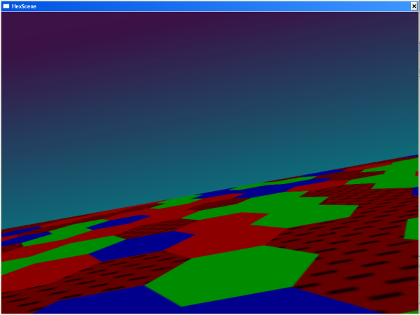
Figure 1: "Hexplane.exe", a demo in which the user flies through 3D space over a hex-based terrain
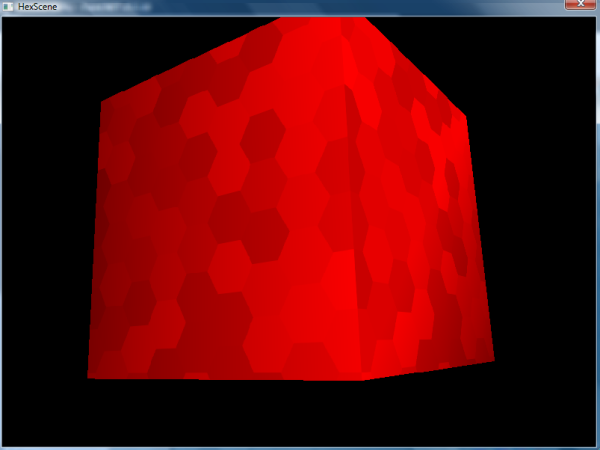
Figure 2: Spinning cube demo with four dynamic hex tessellation surfaces ("Hex3d.exe")
Introduction
Whether called a hex grid, a honeycomb, or a tessellation (which is the mathematical term for a space-filling pattern), groupings of hexagons like the ones shown above are a useful way to fill up two-dimensional space. They provide for a more interesting visual effect than tessellations of 3- or 4-sided polygons; and unlike tessellations composed of several different polygons, hex tessellations create a regular grid with a consistent coordinate system, a fact which has been exploited by all sorts of computer games, and also by many board games.
The work at hand describes how to use a library created by the author to draw a wide variety of hex tessellations. This is accomplished using selected calls into the GDI and GDI+ APIs made by the library. The library is named "hexdll.dll". This somewhat repetitive name makes more sense in the context of its codebase, where it is found alongside "hexdll.cpp", "hexdll.h", "hex3d.cpp", and so on.
The development of the programs provided with this article presented some performance challenges. In one demonstration, a hexagon grid is drawn onto a Direct3D surface. The surface is dynamic; with each frame, a slightly different hex tessellation is drawn, creating an interesting flicker effect. Care was taken to ensure that the many calls into "hexdll.dll" necessitated by this application did not result in decreased frame rate. This requires "hexdll.dll" itself to be capable of operating quickly, and also presents potential interface issues between GDI and Direct3D, which are discussed more extensively further down in the article.
In another of the demo programs, a large hex grid is redrawn in its entirety with each Resize event. Again, if done incorrectly, this action will introduce a very noticeable lag.
These high-performance applications are both enabled by a single common design decision: GDI+ is avoided, in favor of GDI, unless the caller specifically requests anti-aliasing. GDI does not offer this capability, so GDI+ must be used for anti-aliased drawing. However, for drawing operations not involving anti-aliasing, GDI is significantly faster than GDI+. This is an interesting result which is discussed at some length below. Here, suffice it to say that the OOP-style interface exposed by GDI+ comes at a cost, and at a cost which is in some cases dramatic. This article is thus a reminder of the high performance potential of non-OO procedural and structured programming techniques.
Background
The "device context" (DC) is ubiquitous in Windows programming. The Direct3D surface interface used here (IDirect3DSurface91), for example, exposes a GetDC() method. Most Windows controls (be they MFC, Win32, or .NET-based) expose an HWND, which can be converted into a DC using a single Windows API call. Each of these entities is ultimately just a different kind of 2D Windows surface, and "hexdll.dll" can draw hex tessellations on all of them, using the DC as a common medium. Many of these operations are demonstrated in the code base provided, and discussed in this article.
The author's DLL is designed for hassle-free use from native or .NET programs2; the source code provided contains complete examples of both types of clients. The main ".cs" file for the .NET demo is only 87 lines long. None of the C++ demos use more than 450 lines of code, despite their high feature content. The "hex2d.cpp" printer-friendly demo uses only 236 lines of code.
The next section of the article deals with the creation of client apps that use the DLL. For simplicity, a Visual Studio 2010 / C# client app ("hexdotnet.sln" / "hexdotnet.exe") is shown first. The folder tree for this C# application is present in the "hexdotnet" subfolder of the provided source code archive.
After the presentation of the .NET client, the text below continues with the presentation of a variety of C++ client programs, and then concludes with a discussion of the internal implementation of "hexdll.dll". The code for the library is written in C++, and built using the MinGW compiler. Some C++ client apps are discussed as well.
The client programs provided were developed using Visual Studio for the .NET app and MinGW for the C++ apps and for the DLL itself. In constructing the C++ development tool chain, this article relies heavily on techniques described in two previous articles by the same author, GDI Programming with MinGW and Direct3D Programming with MinGW. The text below attempts to be self-contained, but it does make reference to these predecessor articles, as necessary, and they do provide more detailed explanations of some of the background topics for this article. There are some minor differences between the instructions given in this article and those given in its predecessors, due to changes in MinGW. These are discussed in the section titled "Building", further below.
API Selection
The author faced a choice between several 2D drawing APIs in developing the programs described in this article. The APIs considered were GDI, GDI+, DirectDraw, and Direct2D. Of these, Direct2D is the newest and likely the fastest-running alternative. Unfortunately, MinGW does not support it, at least not as downloaded. DirectDraw is, like Direct2D, a component of DirectX, but it is a deprecated one.
Of course, it would be difficult to integrate either of these DirectX-based technologies into typical (i.e., raster-based) Windows applications as seamlessly as was done for the GDI/GDI+ implementation present in "hexdll.dll". Two main advantages of the approach selected are therefore its generality and its lack of bothersome architectural requirements.
Using the Code
One simple way to develop a client application that uses "hexdll.dll" is to use the .NET System.Windows.Forms namespace to create a control onto which the DLL can draw. Any C# application can access the functions exposed by "hexdll.dll". The first step is to insert the declarations shown below into an application class:
 Collapse | Copy Code
[DllImport("hexdll.dll", CallingConvention = CallingConvention.Cdecl)]
static extern void hexdllstart();
[DllImport("hexdll.dll", CallingConvention = CallingConvention.Cdecl)]
static extern void hexdllend();
[DllImport("hexdll.dll", CallingConvention = CallingConvention.Cdecl)]
static extern void systemhex
(
IntPtr hdc, Int32 origx, Int32 origy, Int32 magn, Int32 r, Int32 g, Int32 b, Int32 coordx, Int32 coordy, Int32 penr, Int32 peng, Int32 penb, Int32 anti );
In the C# application provided, these declarations are inserted directly into the Form1 class, very near the top of "Form1.cs". The systemhex(), hexdllstart(), and hexdllend() functions are therefore accessible as static methods of the Form1 class.
At runtime, "hexdll.dll" must be present in the same folder as the .NET executable ("hexdotnet.exe" here), or at least present in the Windows search path, for this technique to work.
In the declarations shown above, note that the Cdecl calling convention is used, as opposed to the default Stdcall option. Programmers uninterested in this distinction can simply copy the declarations as shown above without giving this any thought. For those interested in detail, the author found that using Stdcall in the DLL implementation code caused MinGW to engage in some undesirable name mangling. The DLL function names ended up looking like hexdllstart@0.
The Stdcall convention uses these extra suffixes to support function name overloading; Cdecl does not support overloaded functions and therefore does not require them. It is worth noting, too, that this sort of name mangling is an inherent requirement for the linkage of C++ class methods; the library presented here thus makes no attempt to expose an OO interface.
Calls to functions hexdllstart() and hexdllend() must bracket any use of "hexdll.dll" for drawing. These functions exist basically to call Microsoft's GdiplusStartup and GdiplusShutdown API functions, at app startup / shutdown. This design is in keeping with Microsoft's guidelines for the construction of DLLs that use GDI+.
The actual hex-drawing code in each client app consists of call(s) to systemhex(). In this identifier, the word "system" refers not to some sort of low-level privilege, but to the system of coordinates created by a hex tessellation. Any such tessellation has a hexagon designated (0,0), at its top / left corner. Unless the tessellation is exceedingly narrow, there is a (1,0) hexagon to its right. Unless the tessellation is very short, there is a (0,1) hexagon beneath the (0,0) hexagon.
The figure below shows an example hex tessellation with several of its constituent hexagons labeled with their (X,Y) coordinates, as defined in the system used by "hexdll.dll". In this figure, many arbitrary but necessary decisions made by the author are evident. The placement of the origin at the top left is an obvious example. More subtly, note that the entire grid is oriented such that vertical columns of hexagons can be identified (e.g., the column of hexagons with "X" coordinate 0). The grid could be rotated 90 degrees such that these formed rows instead, but this is not the orientation used here. Finally, note that hexagons at odd "X" coordinates, by convention, are located slightly lower in the "Y" dimension than those at even "X" coordinates. This is another one of these arbitrary decisions made by the author, each of which will potentially impact the implementation of any application that uses "hexdll.dll".
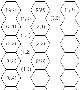
Figure 3: Coordinate system used by "hexdll.dll"
Returning to the declaration of systemhex(), the coordx and coordy parameters to this function define the coordinate of the single hexagon drawn by each call to systemhex(). This (X,Y) point defines the entire hexagon in terms of a coordinate system like the one shown in the figure above. The specifics of this coordinate system are passed in parameters origx, origy, and magn. The origx and origy parameters, taken together, define where the leftmost vertex of the hexagon (0,0) is located. These coordinates are expressed in pixels, relative to coordinate (0,0) of the surface onto which the hexagon is being drawn.
The magn parameter defines the size of each hexagon. Each hexagon is 2.0 * magn pixels wide. Each hexagon's height is slightly less than that, at approximately 1.7321 times magn. (This is 2.0 * sin(60o)) * magn.)
Two RGB color triads are passed to systemhex(): parameters r, g, and b define the interior color of the hexagon, while penr, peng, and penb define the color of its single-pixel outline. Each of these parameters can range from 0 to 255.
Finally, the IntPtr parameter to systemhex() is a HANDLE to the DC to be drawn upon. In the .NET example client provided, this is obtained by taking the Handle property of a Panel control created for this purpose, and passing it to the Win32 GetDC() function. This function is brought into the .NET program using a DllImport declaration very similar to the three already shown, along with the corresponding cleanup function ReleaseDC():
Collapse | Copy Code [DllImport("user32.dll")]
static extern IntPtr GetDC(IntPtr hWnd);
[DllImport("user32.dll")]
static extern bool ReleaseDC(IntPtr hWnd, IntPtr hDC);
In the .NET example program, the MakeHex() method of Form1 does the actual drawing. It is deliberately ill-behaved, redrawing an 80 x 80 hex coordinate system in its entirety. Because MakeHex() gets called one time for every Resize event, this presents severe performance issues unless each call to systemhex() executes with sufficient speed. The code for MakeHex() is shown in its entirety below:
Collapse | Copy Code private void MakeHex()
{
IntPtr h = GetDC(this.panel1.Handle);
for (int row = 0; row < 80; ++row)
for (int col = 0; col < 80; ++col)
systemhex(h, 30, 30, 10, 255, 255, 255, row, col, 255, 0, 0, 0);
ReleaseDC(this.panel1.Handle, h);
}
Above, note that each hex drawn is part of a system having its (0,0) hex at raster coordinate (30,30). This is measured in pixels from the top left corner of Panel1, which is configured to fill the entire client area of Form1. Each hex is 20 pixels wide (twice the magn parameter of 10). The hexagons are white (red=255, green=255, blue=255), with a bright red outline. A full 6400 hexagon is drawn with each call to MakeHex(); an 80 x 80 grid of hexagons is drawn, at system coordinates (0,0) through (79,79). The result of this process is shown below; note that the window is not sufficiently large at this point in time to show the entire 80 x 80 grid:
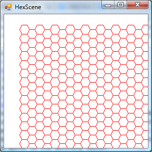
Figure 4: "Hexdotnet.exe" at startup (not anti-aliased)
As the code exists in the download provided, the final parameter to systemhex(), named anti, is set to 0. This disables anti-aliasing and allows for GDI (as opposed to GDI+) to be used, which is key to obtaining good Resize performance. The tradeoff is a somewhat jagged rendering, as evident in the picture above.
If anti is set to a non-zero value, and the .NET example client is recompiled, then a significant performance lag will be perceptible when resizing Form1. In the author's test, a simple maximize operation performed immediately after app startup took about 2 seconds with anti-aliasing enabled.
Significantly, GDI's performance advantage was present even when compared to GDI+ running without anti-aliasing enabled (i.e., with SmoothingModeHighSpeed in effect). If OVERRIDE_C_GDI is defined when "hexdll.cpp" is built, GDI+ will be used for all calls. The resultant performance lag is, again, quite perceptible, and the author provides this option only for performance testing.
Building
The Build Script
The C# demonstration described in the last section can be built and executed by simply opening "hexdotnet.sln" and pressing F5. A pre-built copy of the DLL is included along with its source code.
The DLL can be rebuilt, though, along with all of the C++ demonstration programs, using the build script "make.bat". This batch file also copies "hexdll.dll" to the requisite locations under the "hexdotnet" folder tree.
The script "clean.bat" is also provided; it removes all traces of the build process, except for the pre-built version of the DLL included with the .NET solution. These are intended for execution from a Command Prompt window, not directly from Explorer or Task Manager. Before attempting to run "make.bat", it is necessary to include the MinGW binary path in the environment PATH, e.g.:
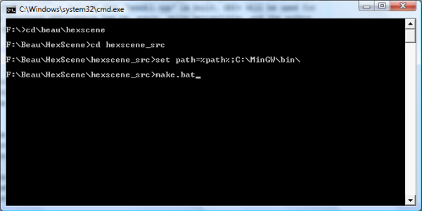
Figure 5: C++ Build Steps
A batch file that sets PATH properly is also provided in the source code archive. It is named "envvars.bat". This can be run instead of the set command shown above.
The build script itself consists mostly of calls to g++. The commands that compile "hex3d.cpp" and "hexplane.cpp" rely on build commands that are very similar to those shown in Direct3D Programming with MinGW. The commands that build "hexdll.dll" itself rely heavily on the MinGW / GDI+ build instructions given in GDI+ Programming With MinGW, and also on some detailed instructions for DLL construction given by the developers of MinGW.
In all of the "g++" commands in "make.bat", the -w option is used to disable warnings. In the versions of MinGW used by the author, this either had no effect, i.e., there were no warnings even without -w, or, if there were warnings, they came from Microsoft's DirectX source files.
MinGW Version Differences
The author used the November, 2011 release of MinGW during the final development of the code supplied, with the MinGW Developer Toolkit selected for inclusion during installation. Slightly different techniques were necessary with earlier versions of MinGW.
GDI+ headers are now included in the distribution, and do not have to be obtained from elsewhere, for example. These headers are in a "gdiplus" subfolder, though, which must be considered in constructing one's #include directives.
Also, it used to be possible to run the MinGW compiler without including "c:\mingw\bin" (or equivalent) in the search path. In the latest versions of MinGW, this will result in missing dependency errors when attempting to use "g++.exe".
Some of these earlier techniques were used in GDI+-Programming-With-MinGW and Direct3D Programming with MinGW, and the instructions given in these articles remain valid when the compiler actually recommended in those specific articles is used.
C++ Demonstrations
At a high level, the steps necessary to create a client application for "hexdll.dll" are the same in both C# and C++. In both cases, the DLL itself must be present alongside the client EXE at runtime (or, at least, in its search path). Similarly, in both C# and C++ clients, a sort of function prototype or stub declaration is inserted into the client code base, to represent the DLL functions. Once these preconditions are met, the DLL functions can be called exactly like the functions (in the case of C++) or methods (in C#) implemented in the client code.
In the C++ client code written here, these declarations are brought into the code base from a header file, "hexdll.h", using #include. This is a very typical way for C++ programs to share declarations, and to, in this way, expose interfaces to each other. The C++ declarations comprising the external interface of "hexdll.dll" are shown below. This is the core of "hexdll.h":
Collapse | Copy Code void HEXDLL systemhex(HDC hdc,int origx,int origy,int magn,int r,
int g,int b,int coordx,int coordy,int penr,int peng,int penb,BOOL anti);
void HEXDLL hexdllstart();
void HEXDLL hexdllend();
These declarations are analogous to the C# declarations of systemhex(), hexdllstart(), and hexdllend(), shown earlier. The HEXDLL macro evaluates, when included in a client application, to __declspec(dllimport), a Windows-specific modifier for functions imported from a DLL. During the DLL build, HEXDLL evaluates to __declspec(dllexport); this is all managed using the preprocessor macro BUILDING_HEXDLL.
When included by a C++ compilation unit, the declarations shown above get wrapped in an extern "C" block. This action is based on the fact that __cplusplus is defined. The extern "C" block ensures that the Cdecl calling convention is used, even in C++ programs, and that names are not mangled. Finally, all of this code is bracketed by an #ifdef directive designed to keep these declarations from getting repeated due to preprocessor actions. Of course, the author of the client application needs only to #include the header file and call its functions.
In neither (C++ / .NET) case does the client application code need to make any direct reference to the GDI+ libraries. Rather, they are included indirectly, as a part of "hexdll.dll".
Spinning Cube Demo
Three C++ example programs are provided with the article. First, "hex3d.exe" is a variation on the spinning cube demo shown in Direct3D Programming with MinGW. This is the application shown earlier in Figure 2. It is built from a single source code file, "hex3d.cpp". In this program, a static texture is not used for the cube surfaces. Instead, with each iteration of the rendering loop, a DC is obtained for the texture's main appearance surface, and is drawn on using systemhex(). Random shades of red are used for each hexagon, resulting in an appealing frame-by-frame flicker effect. The application exits after a certain number of frames have been rendered (by default, a thousand frames). This allows for easy determination of frame rate, by timing the demo's execution time.
The code to get a DC from a texture surface is a new addition to "hex3d.cpp", compared to its spinning cube predecessor. This task is performed by the function do2dwork, shown below this paragraph. This function is called with each iteration of the main loop, prior to the call to render().
Collapse | Copy Code void do2dwork()
{
IDirect3DSurface9* surface=NULL;
hexgridtexture->GetSurfaceLevel(0, &surface);
HDC hdc;
surface->GetDC(&hdc);
for(int hexcx=0;hexcx<TESSEL_ROWS;++hexcx)
{
for(int hexcy=0;hexcy<TESSEL_ROWS;++hexcy)
{
int red=(rand()%(256-MIN_HEX_RED))+MIN_HEX_RED;
systemhex
(
hdc,
TESSEL_ORIG_X,
TESSEL_ORIG_Y,
TESSEL_MAGNITUDE,
red,0,0,
hexcx,hexcy,
red,0,0,0
);
}
}
surface->ReleaseDC(hdc);
surface->Release();
}
The first four lines of code in the function body above serve to get the necessary DC handle for systemhex(). The loop immediately after that is very similar in its implementation to the C# loop from MakeHex(). The color randomization code in the loop body is new, but straightforward. As is typical of C++ compared to C#, the final two statements above clean up resources.
Like "hexdotnet.exe", "hex3d.exe" expects "hexdll.dll" to be present in the current search path at runtime. In addition, it requires the file "hex3d.png" to be present. This contains appearance information for the static texture applied to the top and bottom of the demo solid.
"Hexplane.exe"
This demonstration program creates an illusion of flight in 3D space, above a flat terrain covered by a hex tessellation. The program is built from a single source code file, "hex3d.cpp". It is shown in action in Figure 1, near the top of the article. In this demo, flight takes place in the positive "Z" direction (forward), with rotation about the "Z" axis occurring throughout the flight. Movement continues at an accelerating (but limited) rate until shortly after the terrain below passes out of view. At that point, the demo restarts. The sky is simulated by applying a horizon image to a rectangular solid off in the distance. Like the spinning cube demo, "hexplane.exe" exits after a set number of frames have been rendered.
In many ways, this demo is a simplification of the spinning cube demo. Only two rectangular faces must be drawn, versus six in the spinning cube demo. The declaration of the eight vertices required to draw these two rectangular faces is shown below:
Collapse | Copy Code MYVERTEXTYPE demo_vertices[] =
{
{ -SKY_SIZE, SKY_SIZE, SKY_DISTANCE, 0, 0, -1, 0, 0 }, { SKY_SIZE, SKY_SIZE, SKY_DISTANCE, 0, 0, -1, 1, 0 },
{ -SKY_SIZE, -SKY_SIZE, SKY_DISTANCE, 0, 0, -1, 0, 1 },
{ SKY_SIZE, -SKY_SIZE, SKY_DISTANCE, 0, 0, -1, 1, 1 },
{ -GROUND_SIZE, -GROUND_DEPTH, GROUND_SIZE, 0, 1, 0, 0, 0 }, { GROUND_SIZE, -GROUND_DEPTH, GROUND_SIZE, 0, 1, 0, 1, 0 },
{ -GROUND_SIZE, -GROUND_DEPTH, -GROUND_SIZE, 0, 1, 0, 0, 1 },
{ GROUND_SIZE, -GROUND_DEPTH, -GROUND_SIZE, 0, 1, 0, 1, 1 },
};
This declaration consists of eight distinct vertex structures, each occupying its own line in the code. Each of these begins with "X", "Y", and "Z" coordinates. These coordinates are defined using preprocessor constants that hint at their purposes. More details about the actual design of 3D solids is available in Direct3D Programming with MinGW; the ground face is roughly analogous to the top face of the original spinning cube, and the sky face is analogous to its front.
The remainder of the initializers are explained by the declaration of MYVERTEXTYPE, the custom vertex struct used by both of the Direct3D demo programs presented here. This declaration is shown below:
Collapse | Copy Code struct MYVERTEXTYPE {FLOAT X, Y, Z; D3DVECTOR NORMAL; FLOAT U, V;};
Note that immediately after the coordinates comes the normal vector, followed by 2D point (U,V). The normal vector extends outward into space from the solid, and is perpendicular to the face; this is necessary for lighting purposes. For the ground face, the normal vectors are <0,1,0>, i.e., a vector sticking straight up in the "Y" dimension. For the sky face, the normal vectors point at the user, i.e., in the negative "Z" direction. They thus have a value of <0,0,-1>.
Point (U,V) maps the vertex to a point on the 2D surface of whatever texture is applied to it. The texture 2D coord system has "U" increasing from top to bottom, and "V" increasing from left to right. Because both rectangular faces are defined as triangle strips, a criss-cross pattern is evident in (U,V), as well as in the "X", "Y", and "Z" coordinates themselves; the vertices do not go around the rectangle from vertex 0, to 1, to 2, to 3; rather, they cross over the rectangle in diagonal fashion between vertex 1 and vertex 2. This is consistent with Direct3D's general expectation that solids be comprised of triangular facets.
Both textures used have a static appearance. As a result,
anti is set to 1; because the hex tessellation is drawn just once, there is no real performance penalty associated with this improvement. There is still a function
do2dwork(), as was seen in "hex3d.cpp", but it is called only once, before the first frame is rendered, to set up the static texture appearance. The code for this function is shown below:
Collapse | Copy Code void do2dwork()
{
IDirect3DSurface9* surface=NULL;
HDC hdc;
planetexture->GetSurfaceLevel(0, &surface);
surface->GetDC(&hdc);
for(int hexcx=0;hexcx<TESSEL_ROWS;++hexcx)
for(int hexcy=0;hexcy<TESSEL_ROWS;++hexcy)
{
switch(rand()%4)
{
case 0:
systemhex(hdc,TESSEL_ORIG_X,TESSEL_ORIG_Y,
TESSEL_MAGNITUDE,255,0,0,hexcx,hexcy,255,0,0,1);
break;
case 1:
systemhex(hdc,TESSEL_ORIG_X,TESSEL_ORIG_Y,
TESSEL_MAGNITUDE,0,255,0,hexcx,hexcy,0,255,0,1);
break;
case 2:
systemhex(hdc,TESSEL_ORIG_X,TESSEL_ORIG_Y,
TESSEL_MAGNITUDE,0,0,255,hexcx,hexcy,0,0,255,1);
case 3:
break;
}
}
surface->ReleaseDC(hdc);
surface->Release();
}
As in "hex3d.cpp", the function begins by obtaining a handle to a DC for the surface's appearance. Again, a tessellation of fixed size is drawn. Here, the randomization component is different; either a red, green, or blue hex can be drawn, or no hex at all can be drawn for a given system coordinate. This allows a default appearance, dictated by file "hexplane.png", to show through. This default appearance is loaded from "hexplane.png" earlier in the startup sequence using a call to D3DXLoadSurfaceFromFile. Preprocessor constants TESSEL_ORIG_X, TESSEL_ORIG_Y, and TESSEL_MAGNITUDE define the coordinate system used for the hex terrain; these were tuned to yield hexagons of an acceptable size, and to achieve full coverage of the ground surface. In particular, slightly negative values are used for TESSEL_ORIG_X and TESSEL_ORIG_Y, to avoid leaving unfilled space around the top and left edges of the tessellation.
"Hex2d.exe"
This demo creates a high-resolution, 8.5" x 11.0" bitmap file. The executable shows a modal message box with the message "DONE!" after it has finished creating the output bitmap file. The bitmap is completely covered by a black and white hex tessellation, drawn with anti-aliasing enabled. If printed, the result could be useful for a board or pen-and-paper game built around a hexagonal coordinate system. This program is built from source code file "hex2d.cpp".
Unlike the other two C++ demos, DirectX is not used here. Rather, GDI and Win32 API calls only are used, in conjunction with calls into "hexdll.dll", to achieve the desired result. Specifically, a starting BITMAP is created. A DC is then obtained, for drawing onto this BITMAP. This DC is passed to systemhex() repeatedly, in a nested for loop, to draw the hex tessellation. Finally, the resultant appearance data after drawing must be written from memory out to a properly formatted bitmap file. This last step in particular requires a significant amount of new low-level code compared to the two 3D C++ demos.
The series of steps outlined in the last paragraph are mostly executed directly from main(). After declaring some local variables, main() begins as shown below:
Collapse | Copy Code hexdllstart();
synchexec("cmd.exe","/c del out.bmp");
synchexec("cmd.exe","/c copy blank.bmp temp.bmp");
hbm = (HBITMAP) LoadImage(NULL, "temp.bmp", IMAGE_BITMAP, 0, 0,
LR_LOADFROMFILE | LR_CREATEDIBSECTION);
if(hbm==NULL) {
MessageBox(0,"BITMAP ERROR","Hex2D.exe",
MB_APPLMODAL|MB_SETFOREGROUND);
return 1;
}
The two calls to synchexec() (a wrapper for ShellExecuteEx()) serve to delete "out.bmp", which is the program output file, and then to create working bitmap file "temp.bmp". Note that this working file is a copy of "blank.bmp", which is a plain white bitmap having 16-bit color depth (like the output bitmap). In the application code as provided, this is just a starting point, which is completely overwritten using systemhex calls.
The main() function continues as shown below:
Collapse | Copy Code static BITMAP bm;
bm.bmBits=bigbuff;
GetObject
(
(HGDIOBJ)hbm, sizeof(BITMAP), (LPVOID)&bm );
This code snippet takes the HBITMAP value hbm, which is a pointer-like identifier for a structure held by Windows, and converts it into a BITMAP object proper, present in the static storage of "hex2d.cpp". Getting the actual BITMAP structure (vs. an HBITMAP) is useful as a way to access some properties like width and height using "dot" operator. Variable bigbuff, which is declared with a static size equal to the known memory requirements of the high-resolution bitmap, holds the local copy of the BITMAP appearance information.
Next, main() continues with the code shown below:
Collapse | Copy Code hdc=CreateCompatibleDC(hdctemp=GetDC(0));
ReleaseDC(0,hdctemp);
SelectObject(hdc,hbm);
The series of calls shown above first create a new and independent DC, as opposed to one obtained for a control or window. The DC created is compatible with the desktop (HWND zero), since there is no app main window DC to pass instead. Then, the code associates this DC, and the drawing about to happen, with hbm. Now, with this relationship established, the actual hexagon drawing can take place, with the newly created DC passed as the first parameter to systemhex():
Collapse | Copy Code for(int ccx=0;ccx<HEX_GRID_COLS;++ccx)
{
for(int ccy=0;ccy<HEX_GRID_ROWS ;++ccy)
{
systemhex( hdc,
X_ORIG,Y_ORIG,
HEX_RADIUS,
BRUSH_RED,BRUSH_GREEN,BRUSH_BLUE,
ccx,ccy,
PEN_RED,PEN_GREEN,PEN_BLUE,
1 );
}
}
This code fragment is very reminiscent of the earlier demos. Note that the last parameter is 1, indicating that anti-aliasing is enabled. All of the other parameters are constants which, as before, were tweaked by the author, based on observation, to yield complete coverage of the target surface.
The remainder of main() writes out the image identified by hbm to a ".bmp" file. This is a somewhat tedious process, which is already well-summarized elsewhere online. One noteworthy addition made for this application is that DPI is explicitly set to 192, using the bit of code presented below. Note that the actual setting involves the somewhat more obscure terminology "pels per meter". Application constant IMG_PELS_PER_METER contains the correct value of 7,560 pels per meter:
Collapse | Copy Code lpbi->bmiHeader.biYPelsPerMeter = IMG_PELS_PER_METER;
lpbi->bmiHeader.biXPelsPerMeter = IMG_PELS_PER_METER;
Several online sources simply set these values to 0. The author wished for a high-resolution, printable image of the correct 8.5" x 11.0" size, though, so setting DPI (or "pels per meter") correctly was deemed necessary.
Library Implementation
Many of the calculations required to draw hexagons will involve real numbers. In order to maximize the accuracy of these computations, and to minimize the number of typecast operations necessary, systemhex begins by converting all of its pixel parameters into doubles, and passing them to an inner implementation function:
Collapse | Copy Code void systemhex(HDC hdc,int origx,int origy,int magn,int r,
int g,int b,int coordx,int coordy,int pr,int pg,int pb,BOOL anti)
{
innerhex(hdc,(double)origx,(double)origy,(double)magn,r,
g, b,coordx,coordy,pr,pg, pb,anti);
}
This inner function translates coordx and coordy (hex system coordinates) into actual screen coordinates. In doing so, it largely just enforces the arbitrary decisions made by the author in designing the coordinate system. Its if, for example, ensures that hexagons at odd "X" coordinates are located slightly lower in the "Y" dimension than those at even "X" coordinates, as is the stated convention of "hexdll.dll":
Collapse | Copy Code void innerhex(HDC hdc,double origx,double origy,double magn,int r,
int g,int b,int x,int y,int pr,int pg,int pb,BOOL anti)
{
if(coordx%2)
abstracthex( hdc,
origx+((double)coordx)*(magn+magn*COS_HEX_ANGLE),
origy+((double)coordy+0.5)*(2.0*magn*SIN_HEX_ANGLE),
magn, r, g, b,pr,pg,pb,anti);
else
abstracthex( hdc,
origx+((double)coordx)*(magn+magn*COS_HEX_ANGLE),
origy+((double)coordy)*(2.0*magn*SIN_HEX_ANGLE),
magn, r, g, b,pr,pg,pb,anti);
}
As shown above, the bottom-level function responsible for drawing hexagons in the internal implementation of "hexdll.dll" is another function called abstracthex(). This lower level function operates in terms of system coordinates (as opposed to the hexagon coordinates shown in Figure 3). The prototype of abstracthex() is shown below:
Collapse | Copy Code void abstracthex(HDC hdc,double origx,double origy,double magn,
int r,int g,int b,int pr,int pg,int pb,BOOL anti)
Note that in performing this final translation into raster coordinates, the geometry of the hexagon must be considered in depth. Figure 6, below, is a useful aid to understanding this geometry:

Figure 6: Hexagon Geometry
The diagram above gives all of the dimensions necessary to implement abstracthex(). The leftmost vertex of the hexagon is, by definition, located at (x,y). This vertex is the first vertex drawn by the abstracthex() function. From there, drawing moves down and right to the next vertex. As shown in Figure 6, the 60° angle is key to these calculations. We can view any side of the hexagon as the hypotenuse of a 30-60-90 triangle. The triangle constructed using dotted lines in Figure 6 is an example of one of these 30-60-90 triangles. The other sides of such a triangle measure cos(60°) times the hypotenuse length (for the shorter side) and sin(60°) times the hypotenuse length (for the longer side). Here, the hypotenuse has length magn, and the two side other than the hypotenuse therefore have lengths of cos(60°)*magn and sin(60°)*magn. The actual measurement shown in Figure 6 is negative, since positive "Y" movement in the Direct3D texture coordinate system is down.
As shown in the picture above, the shorter of these two triangle sides approximates the movement from the first vertex drawn to the second in the "X" dimension. Similarly, the longer of these two sides approximates the movement from the first vertex drawn to the second in the "Y" dimension. As we move from the first vertex drawn at (x,y) to the next vertex, we therefore move cos(60°)*magn pixels in the "X" dimension and sin(60°)*magn in the "Y" dimension. The coordinate of this second vertex is thus (x+cos(60°)*magn, y+sin(60°)*magn).
The next vertex drawn is the one directly to the right of the vertex just drawn. Because the length of the side between these two is magn, the third coordinate is located at (x+cos(60°)*magn+magn, y+sin(60°)*magn).
Instead of passing these coordinate expressions to GDI/GDI+ as shown above, though, the code provided uses a system of running totals, in an effort to minimize repeated calculations. Near the top of abstracthex(), the following initializations are present:
Collapse | Copy Code double cham=COS_HEX_ANGLE*magn;
double sham=SIN_HEX_ANGLE*magn;
double opx=(x+cham); double opy=(y+sham); double opm=(opx+magn); double oms=(y-sham);
After the execution of this code, the first three vertices drawn will have coordinates (x,y). The second will be located at (opx,opy), and the third at (opm,y). The fourth coordinate drawn, at the extreme right side of the hexagon, is just a bit further to the right, at (opm+cham,y). The drawing of the fifth vertex moves back toward the left and up, to (opm,oms). Finally, we move back magn pixels to the left, and draw the sixth vertex at (opx,oms).
Depending on whether or not anti is true, either GDI or GDI+ will be used for the actual drawing operations. In either case, a data structure holding all of the vertex coordinates, in drawing order, is first constructed. For GDI, this is an array of POINT structures, whose construction is shown below:
Collapse | Copy Code POINT hex1[6];
hex1[0].x=(int)(x+0.5);
hex1[0].y=(int)(y+0.5);
hex1[1].x=(int)(opx+0.5);
hex1[1].y=(int)(opy+0.5);
hex1[2].x=(int)(opm+0.5);
hex1[2].y=(int)(opy+0.5);
hex1[3].x=(int)(opm+cham+0.5);
hex1[3].y=(int)(y+0.5);
hex1[4].x=(int)(opm+0.5);
hex1[4].y=(int)(oms+0.5);
hex1[5].x=(int)(opx+0.5);
hex1[5].y=(int)(oms+0.5);
Note that the addition of 0.5 to each term serves to achieve proper rounding; otherwise, the decimal portion of each floating point value (x, y, opx, etc.) would simply be abandoned.
If GDI+ is used, an array of PointF structures is built instead. These structures use floating point coordinates, and no rounding or typecasting is necessary. Their declaration is shown below:
Collapse | Copy Code PointF myPointFArray[] =
{
PointF(x, y),
PointF((opx), (opy)),
PointF((opm), (opy)),
PointF(opm+cham, y),
PointF((opm), (oms)),
PointF((opx), (oms))
};
If GDI is in use, the vertex data structure gets passed to a function named Polygon. The SelectObject API is first used to select a pen with the requested outline color, and then to select a brush with the requested interior color. This series of actions results in a polygon with the requested outline and interior colors.
Under GDI+, two calls are necessary to achieve the same result, one to DrawPolygon() and one to FillPolygon(). It is once again necessary to create both a pen and a brush, with the first of these getting passed to DrawPolygon() and the second to FillPolygon(). It should be noted that the necessity of two distinct function calls here plays some role in the relatively slow performance obtained using GDI+. However, the author made a point of running tests with a single call to FillPolygon() only, and GDI+ was still much slower than GDI.
Conclusion
The work presented here led the author to several conclusions about recent versions of Windows, its APIs, and its rendering architecture. GDI, of course, is much more efficient than GDI+. This should be no surprise, given that much of GDI was originally written to work well on the relatively primitive hardware that ran the earliest versions of Windows.
GDI+ is useful primarily because of its anti-aliasing capability. It also offers a cleaner interface than GDI, e.g. in the area of memory management. This OO interface comes at a significant cost, though. Comparable operations are much slower in GDI+ than in GDI, even with anti-aliasing disabled.
While both imperfect, GDI and GDI+ do seem to complement each other well. In the demonstration programs provided, GDI+ works well for generating a high-quality printable image, and this, fortuitously, is not a task that needs to happen with incredible quickness anyway. GDI, on the other hand, provides the high level of speed and efficiency necessary for the dynamic texturing demo ("hex3d.exe"), and in this arena its lack of anti-aliasing will usually go unnoticed. The texture will be moving quickly at runtime, and will also get passed through the Direct3D interpolation filters necessary to scale the texture for each frame. Whatever jagged edges GDI might generate compared to GDI+ are quite likely lost in the translation and animation process.
Finally, some conclusions about combining Direct3D and GDI in the latest versions of Windows were reached by the author in preparing this work. While the changes in GUI rendering that came with Windows Vista were significant, nothing in them seems to rule of the possibility of using GDI to draw on Direct3D surfaces with a level of efficiency that is at least reasonably good. The process of obtaining the necessary DC remains quick and intuitive, and the GDI operations themselves seem mostly to be fast enough to keep up with Direct3D.
Footnotes
- MinGW did not support later versions of DirectX when the article was written. At least, DirectX 9 was the newest version for which headers were present in "c:\mingw\include\", and web searches yielded no obvious way to incorporate later versions. Microsoft's "August 2007" version of the DirectX SDK should therefore be installed in order to build the 3D demonstration programs. Detailed instructions for obtaining and installing the SDK are given in Direct3D Programming with MinGW.
- At present, only 32-bit client applications are supported. To support 64-bit clients would require the code for "hexdll.dll" to be rebuilt in a 64-bit development environment. While there is no reason to suspect that this would not work, 64-bit compilation has not been tested.
History
This is the second major version of this article. Compared to the first version, some improvements in formatting and clarity have been made. The code and binary files have not changed.

