
도전2022
waymo open dataset 본문
https://waymo.com/open/data/perception/
Perception


Here is some information explaining the specs and formats of the perception dataset.
Check out the sections on our latest v1.3 release with key points, 3D semantic segmentation, and 2D-3D association labels!
Also check out the benchmarks based on this dataset: 2022 Challenges with prizes: 3D Semantic Segmentation, 3D Camera-Only Other leaderboards: Real-time 3D Detection, Real-time 3D Tracking, 2D Detection, 2D Tracking, and Domain Adaptation.
Tutorial
If you'd prefer to jump right in, check out the tutorial in Colab. The GitHub repo also includes a Quick Start with installation instructions for the Open Dataset codebase.
Data Labels
The perception dataset contains independently-generated labels for lidar and camera data, not simply projections.

3D Lidar Labels
We provide 3D bounding box labels in lidar data. The lidar labels are 3D 7-DOF bounding boxes in the vehicle frame with globally unique tracking IDs.
The following objects have 3D labels: vehicles, pedestrians, cyclists, signs.
The bounding boxes have zero pitch and zero roll. Heading is the angle (in radians, normalized to [-π, π]) needed to rotate the vehicle frame +X axis about the Z axis to align with the vehicle's forward axis.
Each scene may include an area that is not labeled, which is called a “No Label Zone” (NLZ). These capture areas such as the opposite side of a highway. See our label specifications document for details. NLZs are represented as polygons in the global frame. These polygons are not necessarily convex. In addition to these polygons, each lidar point is annotated with a boolean to indicate whether it is in an NLZ or not.
Our metrics computation code requires the user to provide information about whether the prediction result is overlapping with any NLZ. Users can get this information by checking whether their prediction overlaps with any NLZ-annotated lidar points (on both 1st and 2nd returns).
2D Camera Labels
We provide 2D bounding box labels in the camera images. The camera labels are tight-fitting, axis-aligned 2D bounding boxes with globally unique tracking IDs. The bounding boxes cover only the visible parts of the objects.
The following objects have 2D labels: vehicles, pedestrians, cyclists. We do not provide object track correspondences across cameras.
Details
See the label definition proto and the label specifications document for more details.
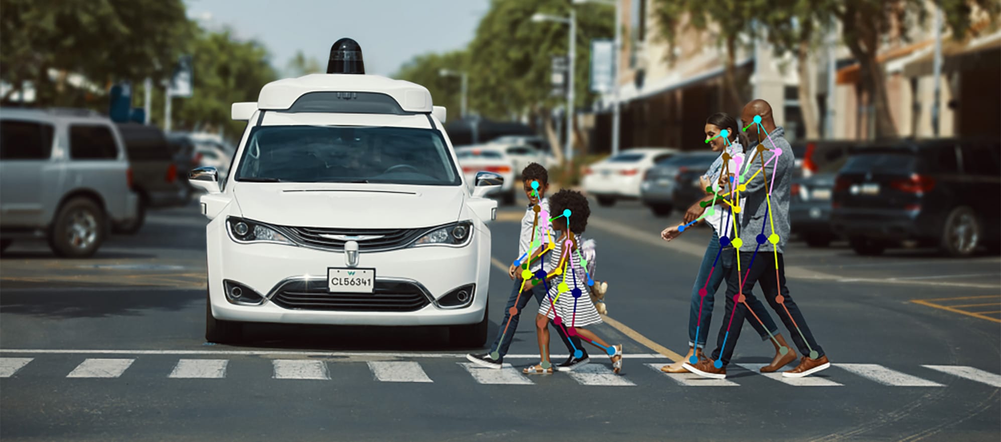
Key Points
We provide a collection of 14 key points from across the human body – including nose, right and left shoulders, elbows, wrists, hips, knees, and ankle – or a select subset of 2D and 3D bounding box labels. For each key point, we also provide a visibility/occlusion attribute. Both types of key points were manually labeled and verified: 2D key points - using camera images, 3D key points - using lidar point clouds. The key points help us understand pedestrian movement, but don’t identify specific individuals.
See the key point definition proto and the tutorial for more details.
2D-to-3D correspondence
Objects labeled on camera images with 2D bounding boxes, which are also labeled with 3D bounding boxes on the lidar point cloud, contain corresponding objects IDs. This correspondence between 2D and 3D bounding boxes was labeled and verified by human operators. Note that due to occlusions and differences in fields of view between camera and lidar sensors some objects do not have this correspondence established.

3D Segmentation
Dense labels for every LiDAR point with rich semantics - 23 classes as listed below. The labels are provided at 2Hz for the entire dataset captured by high-resolution LiDAR sensors.
- 23 classes: Car, Truck, Bus, Motorcyclist, Bicyclist, Pedestrian, Sign, Traffic Light, Pole, Construction Cone, Bicycle, Motorcycle, Building, Vegetation, Tree Trunk, Curb, Road, Lane Marker, Walkable, Sidewalk, Other Ground, Other Vehicle, Undefined
Coordinate Systems
We use the following coordinate systems in the dataset.
Global frame
The origin of this frame is set to the vehicle position when the vehicle starts. It is an ‘East-North-Up’ coordinate frame. ‘Up(z)’ is aligned with the gravity vector, positive upwards. ‘East(x)’ points directly east along the line of latitude. ‘North(y)’ points towards the north pole.
Vehicle frame
The x-axis is positive forwards, y-axis is positive to the left, z-axis is positive upwards. A vehicle pose defines the transform from the vehicle frame to the global frame.
Sensor frames
Each sensor comes with an extrinsic transform that defines the transform from the sensor frame to the vehicle frame.
The camera frame is placed in the center of the camera lens. The x-axis points down the lens barrel out of the lens. The z-axis points up. The y/z plane is parallel to the camera plane. The coordinate system is right handed.
The lidar sensor frame has the z-axis pointing upward with the x/y plane depending on the lidar position.
Lidar Spherical Coordinates
The lidar spherical coordinate system is based on the Cartesian coordinate system in lidar sensor frame. A point (x, y, z) in lidar Cartesian coordinates can be uniquely translated to a (range, azimuth, inclination) tuple in lidar spherical coordinates.
Lidar Data
The dataset contains data from five lidars - one mid-range lidar (top) and four short-range lidars (front, side left, side right, and rear)
For the purposes of this dataset, the following limitations were applied to lidar data:
- Range of the mid-range lidar truncated to a maximum of 75 meters
- Range of the short-range lidars truncated to a maximum of 20 meters
- The strongest two intensity returns are provided for all five lidars
An extrinsic calibration matrix transforms the lidar frame to the vehicle frame. The mid-range lidar has a non-uniform inclination beam angle pattern. A 1D tensor is available to get the exact inclination of each beam.
The point cloud of each lidar is encoded as a range image. Two range images are provided for each lidar, one for each of the two strongest returns. It has 4 channels:
- channel 0: range (see spherical coordinate system definition)
- channel 1: lidar intensity
- channel 2: lidar elongation
- channel 3: is_in_nlz (1 = in, -1 = not in)
Lidar elongation refers to the elongation of the pulse beyond its nominal width. Returns with long pulse elongation, for example, indicate that the laser reflection is potentially smeared or refracted, such that the return pulse is elongated in time.
In addition to the basic 4 channels, we also provide another 6 channels for lidar to camera projection. The projection method used takes rolling shutter effect into account:
- channel 0: camera name
- channel 1: x (axis along image width)
- channel 2: y (axis along image height)
- channel 3: camera name of 2nd projection (set to UNKNOWN if no projection)
- channel 4: x (axis along image width)
- channel 5: y (axis along image height)
A range image represents a lidar point cloud in the spherical coordinate system based on the following rules:
- Each row corresponds to an inclination. Row 0 (top of the image) corresponds to the maximum inclination.
- Each column corresponds to an azimuth. Column 0 (left of the image) corresponds to -x-axis (i.e. the opposite of forward direction). The center of the image corresponds to the +x-axis (i.e. the forward direction). Note that an azimuth correction is needed to make sure the center of the image corresponds to the +x-axis.
Example range image

Camera Data
The dataset contains images from five cameras associated with five different directions. They are front, front left, front right, side left, and side right.
One camera image is provided for each pair in JPEG format. In addition to the image bytes, we also provide the vehicle pose,the velocity corresponding to the exposure time of the image center and rolling shutter timing information. This information is useful to customize the lidar to camera projection, if needed.
