Introduction
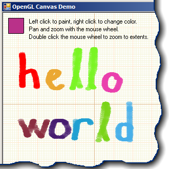
I had recently written some code to display lots of simple 2D shapes for a finite element program. My first thought was to use GDI. However, since I had to display thousands of shapes on the screen, GDI was too slow for me. The solution came up as an OpenGL control. In this article, I will try to explain how I created a control utilizing OpenGL for a 2D shape drawing.
Using the Code
The source code includes a control named GLCanvas2D based on System.Windows.Forms.UserControl. OpenGLspecific initialization code is as follows:
GLCanvas2D::GLCanvas2D()
{
    /* User control initialization code goes here
    ....
    .... */

    // Get a handle to the device context
    mhDC = GetDC((HWND)this->Handle.ToPointer());

    // Choose a pixel format
    PIXELFORMATDESCRIPTOR pfd = {
        sizeof(PIXELFORMATDESCRIPTOR),     // size of the structure
        1,                                 // version
        PFD_DRAW_TO_WINDOW | PFD_SUPPORT_OPENGL | PFD_DOUBLEBUFFER,
                        // flags
        PFD_TYPE_RGBA,                     // pixel type
        32,                                // color bits
        0, 0, 0, 0, 0, 0, 0, 0,            // RGBA bits and shifts
        0,                                 // accumulation buffer bits
        0, 0, 0, 0,                        // accumulation buffer RGBA bits
        32,                                // depth bits
        24,                                // stencil bits
        0,                                 // aux bits
        PFD_MAIN_PLANE,                    // layer type
        0,                                 // reserved
        0, 0, 0                            // layer masks
    };

    // Set the pixel format
    int iPixelFormat = ChoosePixelFormat(mhDC, &pfd);
    SetPixelFormat(mhDC, iPixelFormat, &pfd);

    // Create the render context
    mhGLRC = wglCreateContext(mhDC);
    wglMakeCurrent(mhDC, mhGLRC);
}
This code is called in the constructor of GLCanvas2D. The destructor deletes the render context and releases the device context.
GLCanvas2D::~GLCanvas2D()
{
    wglMakeCurrent(NULL, NULL);
    wglDeleteContext(mhGLRC);
    ReleaseDC((HWND)this->Handle.ToPointer(), mhDC);
}
I have two variables used for panning and zooming the view: a point structure containing a camera position and a zoom factor. In each paint event, the projection matrix is setup using these two variables.
// Set an orthogonal projection matrix
glMatrixMode(GL_PROJECTION);
glLoadIdentity();
glOrtho(mCameraPosition.X -
        ((float)ClientRectangle.Width) * mZoomFactor / 2, // Left
    mCameraPosition.X +
        ((float)ClientRectangle.Width) * mZoomFactor / 2, // Right
    mCameraPosition.Y -
        ((float)ClientRectangle.Height) * mZoomFactor / 2, // Bottom
    mCameraPosition.Y +
        ((float)ClientRectangle.Height) * mZoomFactor / 2, // Top
    -1.0f,     // Near plane
    1.0f);     // Far plane
Camera position and zoom factor are calculated when the user pans (by holding down the mouse wheel) or zooms (by scrolling the mouse wheel). I also needed some method of transforming coordinates from screen to model coordinates and back.
/// <summary>
/// Converts the given point from world coordinates to screen coordinates.
/// </summary>
Drawing::Point WorldToScreen(float x, float y)
{
    // Move the given point to the origin, divide by the zoom factor and
    // add the screen coordinates of the center point
    return Drawing::Point(
        (int)((x - mCameraPosition.X) / mZoomFactor) +
            ClientRectangle.Width / 2,
        -(int)((y - mCameraPosition.Y) / mZoomFactor) +
            ClientRectangle.Height / 2);
}

/// <summary>
/// Converts the given point from screen coordinates to world coordinates.
/// </summary>
Drawing::PointF ScreenToWorld(int x, int y)
{
    // Move the given point to the origin, multiply by the zoom factor and
    // add the model coordinates of the center point (camera position)
    return Drawing::PointF(
        (float)(x - ClientRectangle.Width / 2) * mZoomFactor +
            mCameraPosition.X,
        -(float)(y - ClientRectangle.Height / 2) * mZoomFactor +
            mCameraPosition.Y);
}
GLCanvas2D exposes a Render event which is typically overridden in implementations. The control overrides theOnPaint event of the base class and raises the Render event passing a GLGraphics object as an argument.GLGraphics is similar to the System.Drawing.Graphics class. Drawing is done using the methods of theGLGraphics object.
void MyCanvas2D::Render(System::Object ^ sender, GLView::GLGraphics ^ Graphics)
{
    // Draw a filled rectangle
    Graphics->FillRectangle(0.0f, 0.0f, 100.0f, 50.0f, Drawing::Color::Red);
}
Implementations can also use native OpenGL calls within the Render event.
void MyCanvas2D::Render(System::Object ^ sender, GLView::GLGraphics ^ Graphics)
{
    // Draw a filled rectangle
    glBegin(GL_QUADS);
    glColor3f(1.0f, 0.0f, 0.0f);
    glVertex2f(0.0f, 0.0f);
    glVertex2f(100.0f, 0.0f);
    glVertex2f(100.0f, 50.0f);
    glVertex2f(0.0f, 50.0f);
    glEnd();
}
Points of Interest
If an implementation places more than one instance of GLCanvas2D on a Form, we have to make sure that OpenGLcalls are directed to the correct render context. We achieve this by calling wglMakeCurrent with the handle of our render context each time the OnPaint event is fired.
void GLCanvas2D::OnPaint(System::Windows::Forms::PaintEventArgs^ e)
{
    // Save previous context and make our context current
    HDC mhOldDC = wglGetCurrentDC();
    HGLRC mhOldGLRC = wglGetCurrentContext();
    wglMakeCurrent(mhDC, mhGLRC);

    /* Drawing code goes here
    ....
    .... */

    // Restore previous context
    wglMakeCurrent(mhOldDC, mhOldGLRC);
}
GLView uses OpenGL vertex arrays to speed up drawing. Vertex arrays are handled internally by a customGLVertexArray class. The GLGraphics class collects vertex information using two GLVertexArray's. OneGLVertexArray is used for filled shapes. Each filled shape is converted to triangles and stored in the vertex array. A second GLVertexArray collects lines. No drawing is actually performed until the Render event ends.
System::Void Render()
{
    // Create the vertex arrays on the fly
    float * vp = new float[mVertices->Count * 3];
    float * cp = new float[mVertices->Count * 4];

    // Fill in the vertex arrays. mVertices is an internal list for collecting
    // vertex position and color.
    for (int j = 0; j < mVertices->Count; j++)
    {
        vp[j * 3] = mVertices[j].x;
        vp[j * 3 + 1] = mVertices[j].y;
        vp[j * 3 + 2] = mVertices[j].z;
        cp[j * 4] = mVertices[j].r;
        cp[j * 4 + 1] = mVertices[j].g;
        cp[j * 4 + 2] = mVertices[j].b;
        cp[j * 4 + 3] = mVertices[j].a;
    }

    // Set OpenGL vertex and color pointers to our vertex arrays
    glVertexPointer(3, GL_FLOAT, 3 * sizeof(float), vp);
    glColorPointer(4, GL_FLOAT, 4 * sizeof(float), cp);

    // Draw the arrays
    glDrawArrays(mType, 0, mVertices->Count);

    // Clean up
    delete[] vp;
    vp = 0;
    delete[] cp;
    cp = 0;
}
History
- 25.01.2007 - First release
- 26.04.2007 - Various bug fixes (Thanks to Jac for bug reports and suggestions)
- 05.02.2010 - Fixed a memory leak in
GLGraphics::Render


